


Choosing the Right Antenna for GPR Investigations
The Business of GPR
By Jami Harmon & Mark DeSchepper
Antennas used with ground penetrating radar (GPR) come in different shapes and sizes. The largest antennas typically radiate the lower frequencies necessary to detect the deepest targets. The smallest antennas radiate the highest frequencies that provide the greatest resolution required to detect small, shallow targets. The “best” antenna for a job is the one with the highest frequency that can still detect objects at the desired depth. Mark DeSchepper, President of Kansas-based Echo GPR Services, has more than 12 years of GPR experience and offers some great examples of how to select the right antenna.
Importance of selecting the right antenna for the desired depth
Selecting the right antenna for the depth of the particular target is critical. If the antenna frequency is too high, the maximum detection depth may be less than needed to find the desired target. The GPR image quality deteriorates with increasing depth to the point where no reflections can be observed. Conversely, if the antenna frequency is too low, fine details are lost. For example, if the wrong antenna is used, individual closely-spaced shallow targets cannot be identified because they may appear as a continuous reflection band.
When assessing which antenna to utilize for a job it is essential to consider the surface cover and soil present. One important parameter is the material’s conductivity – How well does the soil, asphalt or concrete let an electrical current pass through it? The higher the material’s conductivity, the more the radar waves are absorbed into the material as they are moving through it. In other words, the radar waves’ depth penetration progressively decreases as the conductivity of a material increases. For example, asphalt typically has low conductivity, while concrete has varying degrees of conductivity depending on its curing state, wetness, and composition. Soil conductivity varies wildly, from radar-friendly sandy soils to radar-foe clay soils.
For this reason, antenna depth specifications are based on the material and application. Antenna specifications for soil-based applications use soil information, while concrete-based applications use typical concrete parameters. Other factors to consider when assessing depth penetration include the presence of metal reinforcing between the surface and the target. The tighter the rebar or mesh spacing (for example, in a concrete slab), the more difficult it is to achieve the desired depth penetration.
A closer look at antenna bandwidth ranges
GPR antennas send out a range of radio frequencies and generally have an ideal frequency at which they transmit most efficiently. This value is based on the size of the antenna’s transmitter and receiver elements and is often referred to as the antenna’s “center-frequency”. Another often-used term is the antenna’s bandwidth, the range of frequencies that the antenna transmits at power levels that are within half the power level radiated at the antenna’s center-frequency. A typical GPR antenna’s bandwidth is about the same as its center frequency.
For example, a 400 megahertz (MHz) GPR antenna will have a center-frequency of 400 MHz and a range of frequencies radiated at power levels within half the power level at 400 MHz – from 200 MHz to 600 MHz. The bandwidth would therefore be 600 – 200 = 400 MHz. Likewise, a 900 MHz GPR antenna could have a bandwidth that extends from possibly 450 MHz to 1350 MHz.
This bandwidth range means that small changes in center-frequency provide minimal enhancement in penetration depth. That is why GPR antennas are not typically available in small frequency increments. More commonly, antennas are available in center-frequencies that are doubled, such as 200 MHz, 400 MHz, 800 MHz, 1600 MHz and 2600 MHz.
Selecting the right antenna
Selecting the right antenna frequency for a GPR job depends on the size and depth of the target. A lower frequency antenna will provide deeper penetration, but the tradeoff is that the targets must be larger to be detected.
When looking only one to two feet beneath the surface, for example, looking for very small reinforcing and conduits, use a higher frequency GPR antenna, which offers greater detail. For deeper targets or characteristics, the primary and secondary choices are lower frequency antennas. These allow users to see deeper, but one trades off the ability to resolve smaller or very shallow features and targets.
When scanning utilities, the mid-range antennas provide sufficient resolution to find four to five inch pipes four to five feet deep. The general rule of thumb for utility locating is a 1:1 ratio; for every foot down, one inch in diameter is required to return a strong hyperbolic reflection of a potential target. To scan deeper, for example, mapping geological features 20-50 feet deep, low frequency antennas will work because very high resolution is not required.
Antenna selection based on a solid understanding of customer goals
According to DeSchepper, antenna selection should be based on a pre-job conversation that establishes an understanding of the depth of the investigation and what the customer wants to accomplish. Comfort, convenience and safety when working on a ladder or overhead is another consideration.
Echo GPR works extensively with electricians and plumbers who are remodeling existing buildings. “We do everything from a local grocery store that wants to install new plumbing in the floor and needs to locate existing utilities and underground conduits – all the way up to nuclear power plants,” says DeSchepper. In addition, the Echo GPR team works in commercial remodels of strip malls, office spaces and office retail spaces, and has performed GPR scans at all the hospitals in Kansas City. They also work for geotechnical and environmental firms to locate underground storage tanks.
DeSchepper explains that grocery stores cannot afford to accidentally cut power to their cash registers. Also, they may have underground refrigeration pipes that run to their coolers. The last thing they want to do is cut into these refrigeration pipes, which would result in downtime, potential environmental issues and even store evacuation.
Here are a few real world examples of antenna selection, taken from the nearly 8,000 GPR scans Echo GPR has performed across the United States.
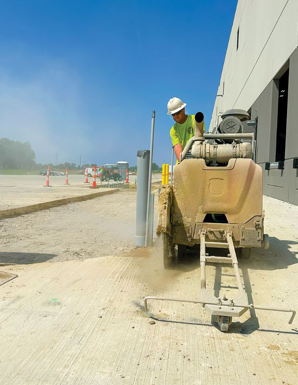
Simple concrete cutting or core drilling
For simple concrete cutting or core drilling, Echo GPR opts for one of the higher frequency antennas, like the 1600 MHz or 2600 MHz antenna. “I usually reach for the 2600 MHz antenna first. This is the highest frequency and gives the highest resolution. But higher resolution gives less depth of investigation. If the project is in a thicker concrete environment, we will switch out to a 1600 MHz antenna, which is a very sharp resolution antenna but can penetrate a bit deeper into the ground,” DeSchepper says.
Working upside down and on a ladder
Currently, Echo GPR is working on a basement remodeling job with a steel erection company locating rebar prior to anchor-drilling steel plates for support mounts. “The engineer elected to hire us because they know that once we have marked out all the steel they can establish where the pre-manufactured supports are and will be able to drill into the ceiling without hitting steel. This speeds up their process.” For this purpose, DeSchepper selected a 2 GHz Palm antenna, which gave him high resolution data with a good depth of penetration, while being extremely lightweight. “I am working upside down and off a ladder, with both hands above my head as I am scanning, so my antenna choice in this case is based on comfort and convenience.”
Locating targets in the Z axis
The Palm antenna was also key to the success of a project at a local children’s hospital. The hospital was building nine stories of research labs on top of an existing parking deck. Contractors needed to thread new vertical rebar into form savers that were buried in concrete. The form savers have a profile of ¾ to 1 inch in diameter and are capped with a piece of plastic. Contractors could not locate the form savers and called in Echo GPR to help locate them. Using the 2 GHz Palm antenna, Echo located the plastic-capped rebar thread couplers in the Z axis.
Says DeSchepper, “It was so accurate that contractors could hammer drill and find 16-30 rebar couplers in each column. We had scanned 800-900 of these rebar couplers and the contractor later told us we had never missed a piece of post tension cable and only missed two form savers in the entire project. This was gratifying, because the vertical and plastic capped profile is such a hard thing to image.”
Locating sewer lines and drain pipes
According to the contractor, the best antenna choice for customers who want to install new drain lines but do not know where the existing sewer is would be a 400 MHz antenna or the 350 MHz digital antenna with HyperStacking (HS) technology, which allows users to see deeper targets. The resolution may be less than other antenna options, but it allows them to look for larger targets 6 to 8 feet below ground.
Another challenge Echo GPR faces is when they’re asked to look for a clay tile pipe drain line in the clay soil that is prevalent in Kansas City. “In this instance we reach for the newer 350 MHz HS antenna because the digital antenna offers a clearer image than a traditional GPR antenna, as well as a 50 percent improvement in depth penetration. It also works with the newer control unit we use, which has more power and flexibility to find these more difficult to image targets.” Along with locating sewer lines and drain pipes, Echo GPR also uses the 350 MHz HS antenna to locate underground storage tanks.
Sinkholes or underground caves
When working for a geotechnical company at a property where there are sinkholes or underground caves, Echo GPR uses a 100 MHz bistatic antenna, one of the few GPR firms to do so. This enables the company to scan more than 20+ feet down, while mapping out soil layers and deeper anomalies.
Field conditions can make antenna selection more challenging
Selecting the correct antenna for achieving the depth penetration required can sometimes be tricky. This happens with more frequency than might be expected – mainly because actual conditions in the field turn out to be different than those given to the GPR crew by a contractor.
DeSchepper notes, “recently, a contractor asked us to scan a 20 foot by 200 foot area because they needed to cut out a hole and install a new piece of equipment. I grabbed the 2600 MHz antenna, my usual go-to for concrete cutting. Now, when I teach the GPR Certification course to those getting the industry certificate through the Concrete Sawing & Drilling Association (CSDA), the first thing I tell students is that the most important thing when scanning concrete is to find the bottom of the concrete – for both slab-on-grade and suspended slab applications. This lets you know you are seeing what you need to see to assist the cutting/coring contractor. When I scanned with the 2600 MHz antenna, I could not see the bottom of the concrete. This was a definite red flag, since the contractor said the concrete was 8 inches thick and the 2600 MHz was set up to look up to 12 inches deep. I quickly realized this was not the right antenna. I switched out to the 1600 MHz – and lo and behold, the concrete they thought was eight inches thick was actually 18 inches thick!”
DeSchepper was able to call the concrete cutting company before they left the shop; they came out with the right saw and right size blade to cut through the concrete.
Antenna selection should be based on a thorough understanding of what the customer wants to accomplish, as well as comfort and convenience when working on a ladder or overhead. GPR contractors should work closely with their equipment manufacturers, as well as the cutting contractor, to ensure the right antenna is selected for each job based on the desired outcome of the scanning project.
Jami Harmon is the Marketing Operations Manager for CSDA-member company GSSI. She is also a CSDA Board member and Chair of the Marketing Committee. She can be reached at harmonj@geophysical.com. Mark DeSchepper is President of CSDA-member company Echo GPR Services, as well as a CSDA Board member, GPR Instructor and Chair of the CSDA GPR Imaging Committee. He can be reached at mark@echogpr.com.