

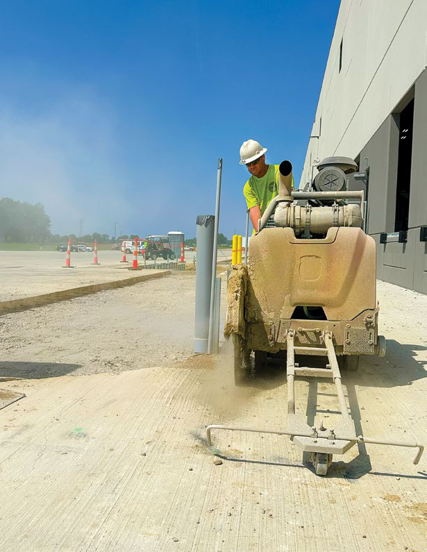


Controlling Concrete Dust
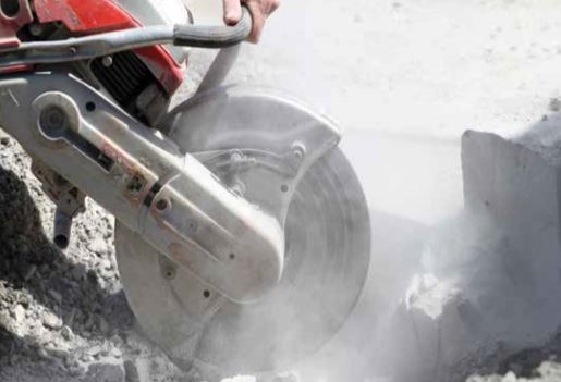
The cutting, coring, grinding and polishing of dry concrete can generate lots of fine concrete dust. The control, collection, handling and disposal of concrete dust is environmentally sensitive with potentially very costly implications. Concrete dust contains silica and Respirable Crystalline Silica (RCS) which are hazardous and regulated by OSHA. The purpose of this document is to clarify many aspects of dry concrete dust control that is presented in an abbreviated form in many documents pertaining to dry concrete dust for a better understanding of those other documents.
NEED FOR DRY CUTTING, CORING, GRINDING AND POLISHING
Frequently the answer to dust control is to use water, but sometimes water is not the preferred method based on other factors and considerations. For example, water (either directly soaked or indirectly splashed or sprayed) can stain certain surfaces, cause damage to materials, and/or get into other areas causing immediate physical or aesthetic damage (including mold). Slurry can be slippery and create slip hazards on jobsites. Water can freeze in cold temperatures. Some coatings, sealers and fillers need clean dry surfaces for an acceptable bond. Water used on some jobs can delay the application of an adhesive, coating or joint-fill material until the surface has completely dried. This can add additional steps to the process to protect surfaces from outside contamination while drying. Concrete should be allowed adequate time to dry and areas that have a film or pool of dried slurry should be cleaned to allow for the appropriate bond from the adhesive, coating or fill material. On some jobsites near live electrical service, electrical safety hazards should be of concern.
SILICA AND HEALTH RISKS ASSOCIATED WITH RCS
Silica is one of the most common materials on the planet. Generally referred to as quartz or sand, silica can be found in many construction materials (in varying degrees of concentration) including concrete, asphalt, stone, bricks, blocks and mortar. When these materials are cut, cored or ground, some of the airborne dust may contain RCS.
The terms “RCS” and “silica dust” are sometimes used incorrectly. “Silica dust” is airborne and contains silica particles (both crystalline and amorphous structures) of varying sizes. “RCS” refers to a very specific subset of silica dust, based on only crystalline structure particles and of a specific size to be considered respirable. Essentially, these are microscopic dust particles.
Health hazards associated with RCS exposure can cause silicosis, lung cancer, Chronic Obstructive Pulmonary Disease (COPD) and tuberculosis infections.
OSHA HIERARCHY (A SERIES OF STEPS)
The first step in elimination is to remove the hazard. One method to remove the hazard of dry concrete dust is to use water for dust control (reference CSDA BP001 Slurry Rev1). The second step is engineered controls (a physical change to the workplace). The use of shrouds, shields and dust skirts will channel the dust generated into the inlet port of a vacuum using the kinetic energy of the tool to drive the dust. The use of positive or negative room pressure to contain the dust in a room. The use of zip walls or physical barriers to contain dust in a room. Ventilation to increase the air exchange in the area to dilute exposure levels. Using remote controls (wireless or tethered) to relocate the operator away from direct exposure to RCS.
Third, administrative or work practice controls (something the employer or worker does). Control access to the worksite. Control RCS exposure of operators by limiting their time performing dust-generating tasks. Good housekeeping practices.
Finally, Personal Protective Equipment (PPE), Including dust masks and respirators. The rating of the respirators is Assigned Protection Factor (APF), and the threshold RCS exposure is APF x PEL.
FINE DUST VACUUMS
Fine dust vacuums used in CSDA-type work are designed to handle a large volume of fine concrete dust. The anatomy of a fine dust vacuum includes the pickup point (wand or shroud), hose, dust debris collection bin/bag/ barrel (tank), filter(s) and motor(s). It is important to understand the fundamental components to select the appropriate fine dust vacuum system for the jobsite requirements.
Vacuums have two distinct and unique performance metrics; the air flow whlich is typically identified in cubic feet of air per minute (CFM) and the suction power (typically measured in inches of water). These two metrics are not measured at the same time. The vacuum typically operates somewhere between these two metrics.
The air flow measurement in the industry is a theoretical value of the air flow in a motor without any restrictions. This is important to understand because the actual flow rate can change with time as dust restricts the flow in the hoses. As a hose bends to follow the path of the machine generating the dust, the bend changes the resistance in flow, leaks at the cuffs and dust settles on the filters. All these factors change the actual air flow measurements. Even the instrumentation to measure the air flow rate is a resistance in the flow. Therefore, the air flow rating on the vacuum is without any restrictions, meaning that attaching a hose or shroud to the vacuum can alter the actual measurement. As dust is carried in the airstream it causes additional restrictions that lower the actual airflow, therefore, the vacuum in CSDA jobsites will rarely operate at an unrestricted full CFM rating.
The suction power rating on a vacuum is a more realistic match to actual performance data. The suction rating is lifting a column of water with full restriction and no air flowing. This is frequently identified as water lift or inches of water lifted. When the vacuum is operating with no air flow (full restriction), no airborne dust will be captured. Therefore, a vacuum in CSDA jobsites will rarely operate at full suction.
Concrete grinding, cutting and coring can produce a lot of dust which is capable of blinding filters. When this dust coats the outer surface of the filters, it momentarily restricts air flow. Vacuum motors are rated as either “thru motors” that use the airstream of the vacuum to cool the vacuum motor, or “bypass motors” that have an external fan to cool the vacuum motor when the airstream is restricted. Typical shop vacuums or general-purpose debris vacuums have thru motors and typical wet vacuums and fine dust vacuums use bypass motors to keep them running cooler, as the airstream is restricted.
The most important component of fine dust vacuums is its filter(s). Visible concrete dust is not respirable and does not pose the same hazards that OSHA regulates in respirable crystalline silica dust. Many shop vacuums and general purpose vacuums do not filter submicron concrete dust particles and only capture visible dust. Unfortunately, this doubles the hazard because the exhaust out of these types of vacuums will contain microscopic dust that is respirable and because the visible dust is removed from the air, the operator may feel safe from exposure hazards and not use a respirator or breathing protection appropriate for that dust hazard.
Fine dust vacuums usually have multistages in the overall filtration. This is pretty typical because the bulk volume of dust consists of large size particles (10 to 100 microns), so it is common to filter out those large particles first before filtering out the finer submicron particles.
Many times the first course filter is a cyclonic or mechanical filter. The dust particles in the airstream flowing through the hose are moving at a high velocity to keep the dust in suspension in the airstream. As the particles enter the cyclonic separator (frequently called a pre-separator) the dust particle velocity is drastically decreased and the dust particles fall out of suspension and settle in the collection drum. The mechanical filter is similar except it is a physical barrier at the end of the hose the particles strike forcing a change of direction as they enter a larger volume chamber and the velocity of the particle is lost as it drops out of suspension. The mechanical filter is also sometimes referred to as a pre-separator because it interrupts the dust in the airstream and, like the cyclonic filter, the velocity of the airstream is greatly reduced causing particles to fall out of suspension and drop.
The primary filtration of a fine dust vacuum is typically a sieve style filter with small openings in the sieve to capture the fine dust particles. In the CSDA industry, the large volume of fine dust generated with cutting, coring and grinding operations can blind small filters to the point of total air restriction. As the filter area is decreased from the blinding, the velocity of the air moving through the smaller available area is increased and can cause the higher velocity particles to penetrate the filter media deeper and cause permanent damage. Larger filter areas are ideal to lower the air/ particle velocity to minimize the penetration into the filter media and the increased area keeps the filter from blinding and minimizing the air flow at the tool.
To keep the fine dust vacuum filters from blinding during operation, there are many techniques that vacuum manufacturers employ including the use of filter cleaning mechanisms, increased filter surface area and/or using pre-separators.
The bag house style filters employ many hanging pleats of filters. As dust cakes on the filter media, the outer layer of dust combined with the large filter area causes a low air/ particle velocity. This minimizes the particle depth of penetration which in return also minimizes the damage to the filter and the weight of the dust releases it as the vacuum is suspended. In other words, when the vacuum is momentarily shut off, the filters practically clean themselves. Most bag house style vacuums are also equipped with a mechanical shaker to shake loose the dust from the pleats. However, the effectiveness of the shaker is increased if the vacuum is suspended because as the dust is shaken free of the filter, the vacuum can quickly suck it back to the filter. Otherwise, if the vacuum is off (momentarily), the particle will drop and settle in the collection tank.
Some bag filters that use a puffy bag material also greatly slow the air/particle velocity by capturing the dust at many points through the bag material while permitting the air flow paths throughout the cross section of the bag. Particles can penetrate the media and permanently damage the filter, so the filter bag should be replaced after each use. Bag filters provide a cleaner disposal method when the dust collection bin needs to be emptied, but this adds cost to the use of the vacuum because bag replacement is required. Bag filters usually use a mechanical filter on the inlet to the bag to prevent the air/particle velocity from tearing the bag material.
Many fine dust vacuums use pleated filter cartridges to have an ideal ratio of filter surface area to the size of the filter space packaged in the vacuum. The cartridges are also very easy to replace and the cartridges can be equipped with a filter cleaning mechanism (either automatic or manual). Some of the filter cleaning mechanisms use a reverse air blast to suspend the vacuum momentarily, blast air pressure in the reverse direction to the normal flow and blow out the dust particles on the filter. This can be done automatically on a timer or manually as needed. A magnahelic gauge can be used to measure the pressure differential across the filter, and some vacuums use an indicator light. The advantage of the magnahelic gauge is that over time the gauge can give the operator the condition of the filter, so they know when it needs to be replaced. The reverse air blast pressure can damage and compromise filters. To minimize filter damage from these blast overpressures, many of the cartridge filters have a cage surrounding the media to protect the filter integrity. Some other filter-cleaning mechanisms include mechanical shakers, strike plates and/or vibrators. All of these can be done manually or automatically.
Most fine dust vacuums are rated as HEPA, or near HEPA filtration levels. The HEPA (High Efficiency Particulate Air) filter is a rating, according to NIOSH/OSHA, for a vacuum capable of filtering out 99.97 percent of the 0.3 micron sized particles of the air that passes through it. Some jobsites require a fine dust vacuum that is only near HEPA filtration levels and typically specified as HEPA-99-percent filtration. It might not filter to the 99.97 percent level of the 0.3 micron sized particles but it will capture the 0.3 micron particles, just a little less efficiently. On some jobsites, this might be good enough. As additional filtration is added, it creates more resistance to air flow and can increase the motor power requirements. It can also decrease the air flow at the pickup point. Either way it could change the size or complexity of the vacuum.
Some jobsites require a “HEPA certified” vacuum which is a vacuum that satisfies certain standards of efficiency that were originally set by the United States Department of Energy (DOE). These include the HEPA filter rating of 99.97 percent of 0.3-micron particles, minimal resistance to the air flow (around 300 pascals pressure drop across the filter at the vacuum flow rating), and finally, assuring that all air goes through the filter (unable to leak around it). After the complete filtration system has been tested and deemed certified, the HEPA rating for that vacuum can be given. Unlike typical sieve filters, the certified HEPA filters use a combination of diffusion, interception, inertial impaction and electrostatic attraction as the mechanisms to trap particles.
Some vacuums use a HEPA filter rating as defined by the European Union in the European Norm EN-1822:2009 that designates a HEPA class rating (like H14, etc.), but this is still not yet fully harmonized to be equivalent to the US HEPA standards.
The dust debris collection bin/bag/barrel (collection tank) can be an important aspect of the CSDA contractor’s administration controls. The size of the collection tank is directly proportional to the weight of the debris. It is also important to have a procedure in place for secondary dust exposure from transferring or emptying the dust bin when the dust is disturbed. Some contractors put the dust bin in a large bag to minimize the dust exposure to the confines of the bag when the bin is emptied.
The hoses are an integral part of the vacuum system as a means to connect the tool generating the dust to the vacuum filters and collection tank. Damage to the hoses can greatly compromise the overall performance of the system. If the hose is kinked or crushed it will increase resistance to air flow. Longer hose runs can also increase resistance to air flow. Smaller diameter hoses increase the air speed to keep the particles in suspension but larger diameter hoses have lower resistance. Holes in the hoses will bypass the air flow available at the collection point at the tool.
If the vacuum hoses are extremely long, the dust can accumulate outside of the airstream and settle in the hose. The settled dust can make the hose heavier to move and increase resistance to air flow. To fully clear the hose, simply walk the hose to the vacuum pushing the dust along the way until it gets to the vacuum inlet.
The high air/particle speeds of dry concrete dust in the vacuum hoses can sometimes build up static electricity. Some vacuums use antistatic hoses or a small sash chain that hangs from the vacuum to help dissipate the static charge.
Vacuum hoses are crush-proof because the vacuum is pulling a negative pressure on the hose. Hoses designed for pumping are designed to withstand high internal positive pressure and would collapse if used on a vacuum with high negative pressure.
Many CSDA contractors use Y-Splitters to use a single vacuum with multiple tools. An example would be using two small chipping hammers with one large high CFM vacuum. One consideration is to have a very short run between the vacuum and the Y-Splitter or increase the diameter of the hose from the Y-Splitter to the vacuum to minimize restriction to air flow.
The Y-Splitter can also be used to increase the CFM of the inlet to the tool by using two smaller vacuums in parallel. The same consideration applies to the hose diameter between the tool and the Y-Splitter. A larger hose diameter and the use of a shorter hose minimizes resistance.
Finally the last part of the vacuum system is the cleaning wand attachment or the pickup point (the location where the tool being used is generating the dust). A restriction at the pickup point will increase the air speed and create a suction to draw in concrete dust particles. An example to visualize this is to remove the dust skirt from a grinder to create a large cloud of dust. Using the same vacuum, replace the skirt with a minimal gap to the slab surface and the high air speed will actually clean the slab surface and the visible cloud of dust might totally disappear.
The energy in the particle of the dust generated by the cutting, coring or grinding is a function of mass and velocity. If a baseball is thrown from the pitcher to the catcher, the wind has little impact on changing the ball’s flight path, unless the wind speeds approach that of a hurricane or tornado. If a ping pong ball is thrown the same way (same speed and distance), even a slight breeze can alter its direction. The shrouds and dust skirts used on CSDA equipment are designed to use the kinetic energy of the particle to assist the dust collection of the vacuum by directing the particles to the vacuum inlet. On down-cut concrete saws, the slot generated by the blade is an escape path for the dust to bypass the collection pickup point of the vacuum unless the collection point is further back on the slot to capture all the lighter weight dust particles (respirable dust consists of light small particles, usually between 0.01 and 5 microns). For up-cut saws, the blade generating the dust can throw the dust into a vacuum port if it is properly directed to the vacuum inlet port. Like the baseball ball analogy, the vacuum may capture the airborne respirable dust (minimizing the RCS hazard), but still leave the larger heavy dust particles on the ground. The large concrete dust particles do not pose the same hazards as the smaller respirable particles.
The CFM requirements of a grinder are directly proportional to the diameter of the dust skirt and the gap between the skirt and the slab surface. It is also affected by the velocity of the particles (high speed grinders, a rotary grinder vs a planetary grinder, etc.) and how well the particles are directed to the vacuum inlet port.
JOBSITE CLEANUP
Airborne concrete dust can float considerable distances before settling, and it can be disturbed time after time making it airborne again and again. It is important to practice good housekeeping methods to ensure vacuums continue capturing the dust to prevent this from happening. Wet concrete slurry will eventually dry out and can turn into dry airborne dust. Even mist that encapsulates concrete dust particles to control RCS exposure will eventually dry out and release the dust into the air.
Dust can be generated by any trade on a same jobsite and potentially impact nearby trades as well. It is important to segregate high exposure areas to protect workers who are unknowingly being subjected to higher dust exposure.
When cleaning slab surfaces for the application of a coating, some contractors use a squeegee with a dry fine dust vacuum instead of a brush with a dry fine dust vacuum, because the brush permits air flow between the bristles and a tight seal from the squeegee to the slab surface can maximize the air speed in that minimal gap and drastically increase the suction on the slab surface at the pickup point. With the squeegee properly used, it can clean the slab surface more efficiently, creating a better bond with the coatings.
For setting anchors, it is important to clean out the hole before the anchor is installed. Many of the anchor manufacturers in the past have suggested using a puff of air to clean out the hole. With the new OSHA silica standard, the use of a HEPA vacuum to clean out those holes will be a new requirement.
In the past, broom sweeping was common on many CSDA jobsites. Under the new OSHA silica standard, vacuums will be used more for general cleanup.
TESTING, MEASUREMENTS AND MONITORING
If OSHA or the owner/prime contractor performs a test, the CSDA contractor should consider independently performing the same test. Sometimes a single test can yield wrong results and without another comparison test it might be difficult to defend against the test.
Table-1 on the OSHA silica standard will help minimize extra testing, measurements and monitoring. Many CSDA tasks and methods that fit best with factors in the job specific requirements might not be on Table-1. Either way, the CSDA contractors will need to perform testing or use objective data from the testing performed by others. It is important to fully understand the testing being performed to be certain it is an appropriate comparison from one job to another.


