


GPR Talk: But Wait, There’s More!
GPR technology has been an accepted and routinely used nondestructive method for imaging objects embedded in concrete prior to cutting or coring for several decades. On July 17, 2009, the CSDA released a Best Practice for GPR Concrete Inspection, CSDA-BP-007. It details the general use of GPR for concrete imaging, normal survey applications, and includes scanning with single sided access and slab-on-grade application. However, it was never intended to outline difficult or challenging survey conditions.
It is not uncommon for concrete contractors to request the location of rebar, conduits, post-tension cables, electrical, or plumbing in order to aid in remediation risks. Additionally, savvy contractors have been using GPR technology to determine concrete slab thickness. This provides the concrete contractor with several benefits including the proper assignment of concrete cutting and coring tools, as well as the ability to better quote the work required. Trained and CSDA Certified GPR operators understand the benefits and limitations of the technology and how to determine the best course of action in challenging survey conditions. Yet, even the most knowledgeable operators will wonder if there’s a tip or trick that they can deploy in the field to collect better data. Here we explore the difference between suspended slab and slab-on-grade surveys, as well as infield processing techniques which operators can use to get the best out of their slab-on-grade data.

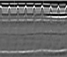
Figure 1: Elevated concrete slab with two layers of rebar.

Figure 2: Reinforced concrete roadway.
The detectability of the slab bottom depends on the underlying material and amount of steel within the slab. It is easier to see when a contrasting material such as water, air or metal is under the slab because they will have a stronger dielectric contrast. In Figure 1, the data is representative of an elevated concrete slab. Note the several hyperbolic reflections on the screen, this is indicative of a double rebar mat. Towards the bottom of the data image, there is a strong dielectric contrast at the concrete-to-air boundary and therefore produces a clear indicator of the bottom of the slab.
In slab-on-grade situations, the bottom may be very weak or invisible if the slab rests on sand or another concrete structure (supporting beam, for instance) with similar
dielectric properties. This can be challenging due to the low dielectric contrast for the concrete-to-sand boundary and intersecting hyperbolic tails from objects embedded in the slab. The former results in weak or non-existent reflections and the latter tends to mask the reflection from the bottom of the concrete interface. Figure 2 illustrates a reinforced concrete roadway with a strong reflective boundary towards the center of the roadway. This is an example of a void. The concrete-to-grade boundary is less reflective as the air-filled void.
Operators can use the following tips for in-the-field manipulation: 2-D versus 3-D Data Collection: In most cases, GPR manufacturers recommend using 2D scanning for real-time locating and simple imaging services, and to use 3D data collection for complex survey sites. However, slab-on-grade surveys are an exception to this rule. It is recommended to conduct 2D scanning in these situations because the layer interface is a planer target which is more easily viewed from the side.
Depth Setting: Conducting a preliminary scan of the area will help the operator determine the appropriate GPR system settings. A common mishap is that the system is set to a depth that is less than the overall concrete depth. This inherently causes data loss at the deeper levels. Remember to always set the depth range 2-3 inches deeper than the expected slab thickness to ensure that the full slab thickness is captured.
Gain: Display Gain and System Gain can be used to brighten a weak back reflection. However, these settings should be used with caution. Display Gain and System Gain settings often influence the rest of the data. Some systems apply a correction factor to gain based on assumed material dielectric. Check with the manufacturer for specific details of your system.

Figure 4: An elevated slab with parallel metal and PVC conduits. Left half of the profile- “standard” antenna position. Right half- same survey line with antenna turned sideways. Red circles define metal targets, unmarked targets are PVC.

Figure 3: Example of migrated GPR data with a Hilbert Transform applied.
Migration: Migration eliminates hyperbolas by collapsing them into dots representing the actual targets. This can be helpful to make target identification more intuitive and makes the data easier to interpret. This is especially true for slab-on-grade because the tails of hyperbolic targets can sometimes intersect and hide the concrete-to-sand boundary reflection. By collapsing the hyperbolas into dots, the bottom of the slab can become more recognizable.
Cross Polarization: When detecting linear metal targets (pipes, rebar, etc.), antenna orientation relative to the target becomes important. Antenna dipoles (transmitter and receiver) are most sensitive to the metal targets that are parallel to them. In other words, if an operator is scanning across the slab with the GPR system in its normal orientation, it is sensitive to targets that are running perpendicular to the direction the operator is moving (parallel to the antenna dipoles).
Some systems can be modified to turn the antenna 90 degrees. This method is known as “cross-polarizing”. If the operator scans over a metal target that is again perpendicular to their
direction of travel, the GPR system is not as sensitive to it. This “weakens” the amplitude of the metallic objects and may result in a stronger concrete bottom reflection.
In summary, GPR interpretation and survey efficiency is a skill that requires training, field experience, time and practice. These tips are intended to help operators troubleshoot a very specific type of survey scenario. An operator may employ all of them, some of them or only one of them in an attempt to conduct a successful survey. In some extreme cases, none of the solutions may work, and only a trained operator will know what tools to use and when. Malcolm Gladwell once said, “Practice isn’t the thing you do once you’re good. It’s the thing that makes you good.”

![New Products & Industry News [Mar ’16]](https://www.concreteopenings.com/wp-content/uploads/2015/02/IB-Banner.jpg)